Automatic rubber-tapping machine
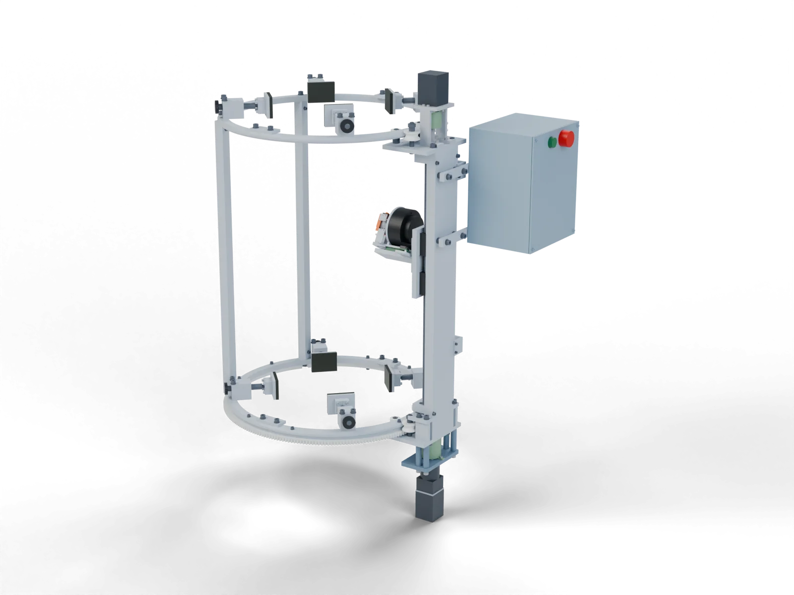
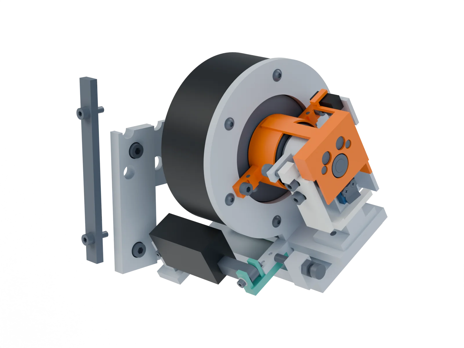
An automated rubber tapping machine mounted on the tree. It carries a small rocking knife around the trunk. We handled the full project, from system architecture to delivering a model tested through simulation for our client.
The problem
Tapping a rubber tree means drawing a blade around a living, uneven trunk at a controlled angle and depth, again and again, without damaging the bark. Done by hand it takes skill and long hours.
The machine has to clamp onto the tree, travel around it and down it, and hold a cutting edge steady against the bark, then pull it safely away.
- Envelope
- About 464 × 694 × 931 mm
- Analysis
- Seven linear-static FEA cases
- Scope
- CAD assembly, drawings and analysis
The architecture
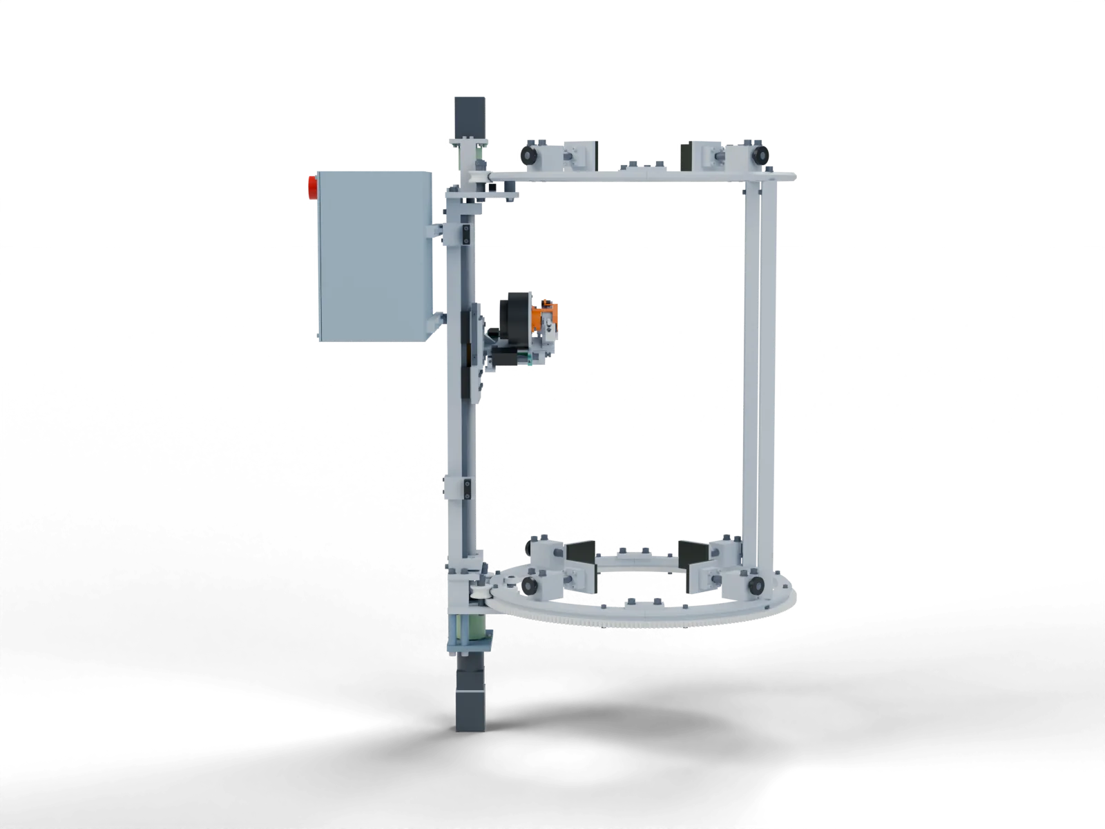
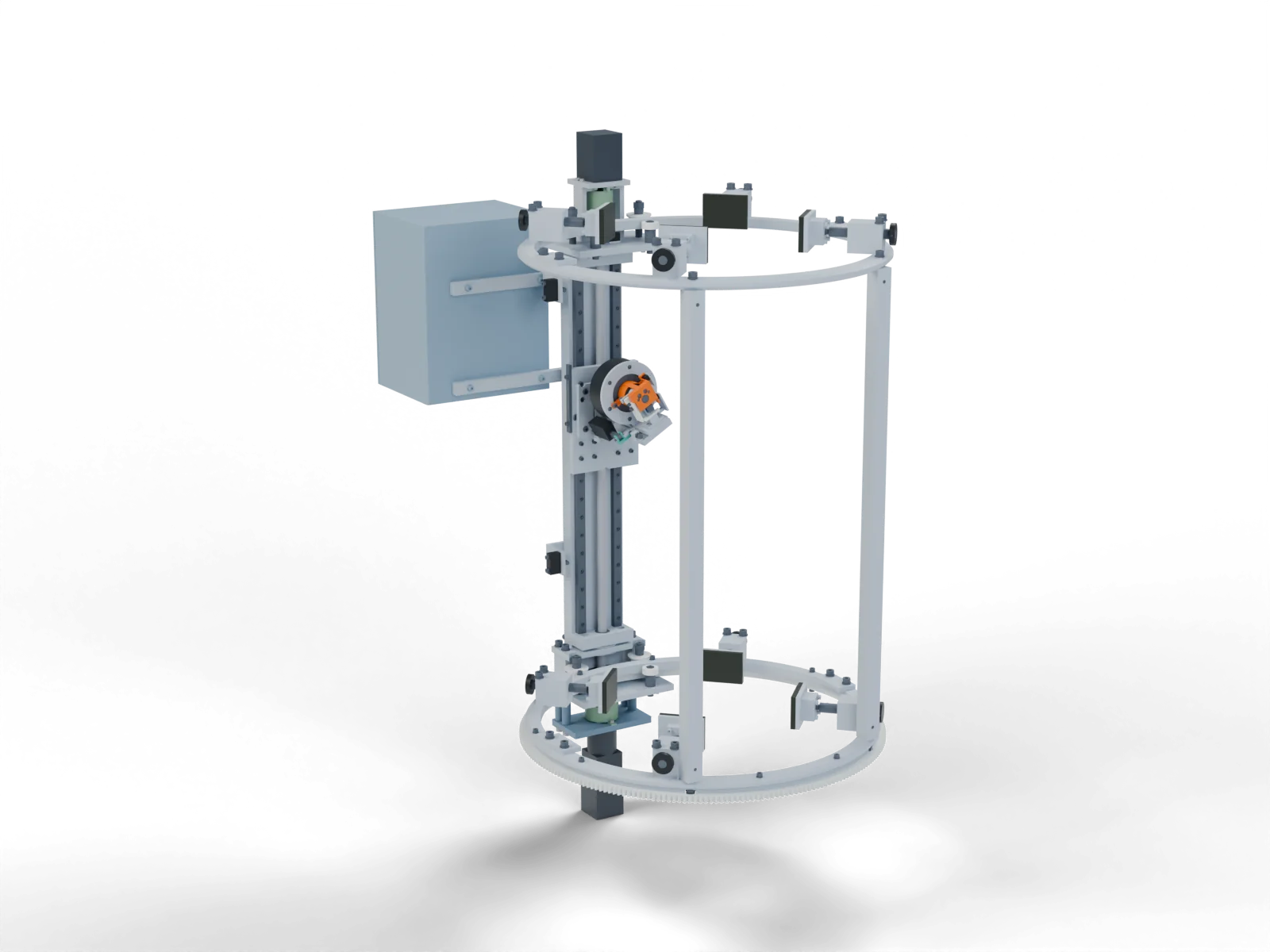
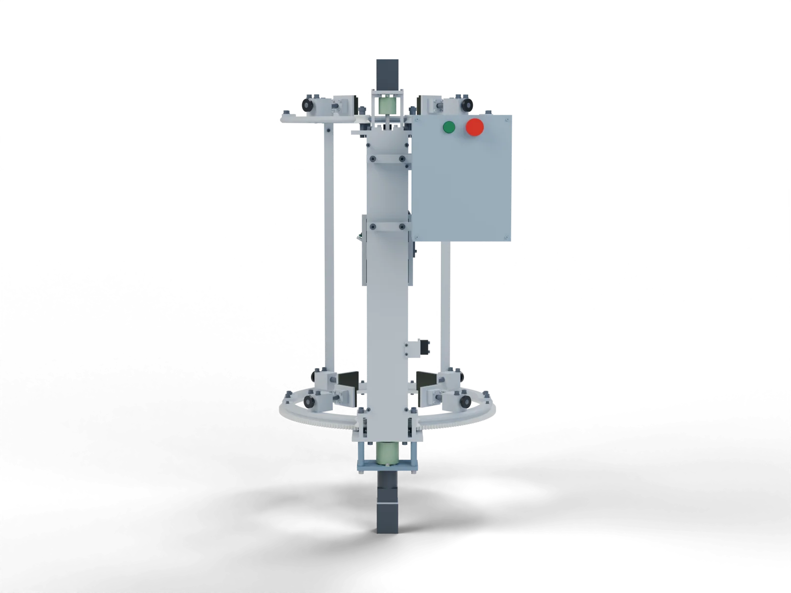
We separated the jobs. Split rings clamp around the trunk on adjustable contact shoes. A carriage travels around the ring, a guided screw drive moves it vertically, and a compact head on the carriage does the cutting. Controls sit in their own steel enclosure on the side.
Keeping mounting, travel and cutting apart makes each one easier to adjust, service and analyse on its own.
The cutting head
The head does two things, independently. A linear actuator moves the whole head 15 mm towards the bark to engage, and the blade rocks ±3° at a 20 mm edge radius to make the cut.
We modelled that motion and checked it in an animated mechanism study before detailing the parts.
The analysis
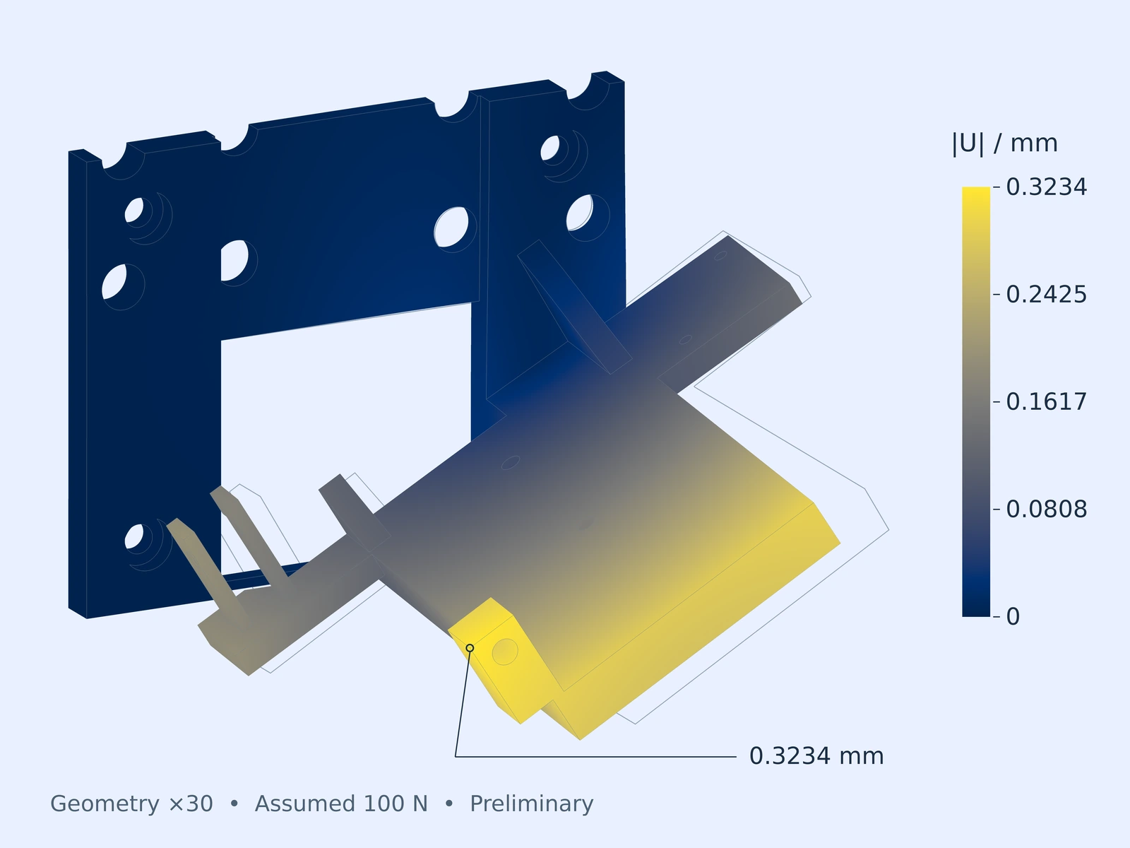
We ran seven linear-static FEA cases on the head’s three critical parts: the blade, the drive shaft and the mounting bracket, each loaded with 100 N at the cutting edge. Each model sets out its supports and load patches explicitly, so the results can be read honestly.
The blade and shaft barely moved, by thousandths of a millimetre. The aluminium bracket deflected about 0.31 mm, far more than anything else.
What it showed
The analysis set the next priority: stiffen the bracket and model how the joints really carry load before treating the assembly as a precision cutting system. Then come refined models, real hardware interfaces and controlled tests.
Alongside the analysis, the assembly is documented in assembly and production drawings.
Start with what you have.
A sketch, a reference, a rough idea. Let’s figure out the next step together.